
- #Digital isolator application notes how to
- #Digital isolator application notes iso
- #Digital isolator application notes plus
- #Digital isolator application notes series
The DCLK is generated by delaying the standard SPI clock by an amount equal to the round trip propagation delay through the isolator. The ADuM3150 generates a delayed clock, DCLK, without the use of an extra isolator channel.
#Digital isolator application notes series
The ADuM3150 ( figure 6) is part of the SPIsolator series of high-speed digital isolators designed to optimise the isolation of SPI buses. Optimising the digital isolator delayed clock implementation Analogue Devices has developed a digital isolator optimised to deliver the highest possible performance in the delayed clock scheme. Thus, using existing isolators will cost more power and board space while still falling short of the maximum possible benefit of the scheme. The extra isolator to delay the clock still consumes around 20-25% more power. The half SPI clock period will be 鈮? ns or 20 ns, resulting in an even faster maximum clock rate of 25MHz.Īlthough the speed and skews of the digital isolators are significantly better than that of optocouplers, timing skews and distortions between channels still limit the maximum possible SPI clock rate. In these cases there is an added benefit. In such three-wire SPI buses, a single quad digital isolator with two reverse channels can be used to implement the SPI bus and the delayed clock. In many applications, the MCU only shifts out data from an ADC and doesn't shift in anything. Given similar timing through all isolator channels, the new SPI half clock period should be 鈮? ns or 25 ns, for a maximum clock rate of 20MHz.
#Digital isolator application notes plus
This prevents isolator prop delay from limiting overall SPI throughput, and now a faster SPI clock is possible that's limited only by mismatches and distortion between the clock and data channels, plus trace, master, and slave delays. Pushing the envelope with high-performance digital-isolation technology (Rev.Consider implementing a delayed clock with an extra isolator channel as per figure 4-at a minimum an additional high speed channel needs to be used. Industrial data-acquisition interfaces with digital isolators (Rev. Staying on budget: How digital isolators are transforming field transmitters Why signal isolation matters in 48-V HEV/EV systems ISO7740-Q1 Functional Safety, FIT Rate, Failure Mode Distribution and Pin FMA
#Digital isolator application notes how to
How to select the right digital isolator for your design Universal Digital Isolator Evaluation Module B)ĭistance Through Insulation: How Digital Isolators Meet Certification Requiremen Introduction to HVDC Architecture and Solutions for Control and Protection (Rev.

Why are Digital Isolators Certified to Meet Electrical Equipment Standards? VDE Certificate for Reinforced Isolation for DIN EN IEC 60747-17 (Rev. Improve Your System Performance by Replacing Optocouplers with Digital Isolators (Rev. UL Certificate of Compliance File E181974 Vol 4 Sec 6 (Rev. TUV Certificate for Isolation Devices (Rev.
#Digital isolator application notes iso
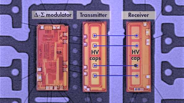
Iso Design W/ 16-kV Contact Discharge ESD Protection ISO774x High-Speed, Robust-EMC Reinforced and Basic Quad-Channel Digital Isolators datasheet (Rev. See the Device Functional Modes section for further details. If the input power or signal is lost, default output is high for devices without suffix F and low for devices with suffix F. The ISO7740 device has all four channels in the same direction, the ISO7741 device has three forward and one reverse-direction channels, and the ISO7742 device has two forward and two reverse-direction channels. These device s come with enable pins which can be used to put the respective outputs in high impedance for multi-master driving applications and to reduce power consumption. Each isolation channel has a logic input and output buffer separated by a double capacitive silicon dioxide (SiO 2) insulation barrier. The ISO774x device s provide high electromagnetic immunity and low emissions at low power consumption, while isolating CMOS or LVCMOS digital I/Os. The ISO7741B device is designed for applications that require basic insulation ratings only. This family includes devices with reinforced insulation ratings according to VDE, CSA, TUV and CQC. The ISO774x device s are high-performance, quad-channel digital isolator s with 5000 V RMS (DW package) and 3000 V RMS (DBQ package) isolation ratings per UL 1577. Automotive version available: ISO774x-Q1.Wide-SOIC (DW-16) and QSOP (DBQ-16) package options.☘ kV IEC 6 contact discharge protection across isolation barrier.System-level ESD, EFT, and surge immunity.Robust electromagnetic compatibility (EMC).Low propagation delay: 10.7 ns typical (5-V Supplies).Low power consumption, typical 1.5 mA per channel at 1 Mbps.Default output high ( ISO774 x) and low ( ISO774 xF) options.


 0 kommentar(er)
